Introduction
 Getting more familiar? Excellent!
Note
All the code and resource files in this post are available on my GitHub page, because it’s fun to share.
Welcome to part 3 of this series. We are going to look at the basic functions of the VDC, which enables 80 column support. It is foremost a chip designed to do nice stuff with text. It can do interlaced modes and bit-mapped graphics though, and we might take a look at that later on.
The bitmap mode has enabled people to create games for it which are not dependent on the hardware sprites and other VIC-II effects. For instance, someone has ported Ultimate games to the C128 using this mode:
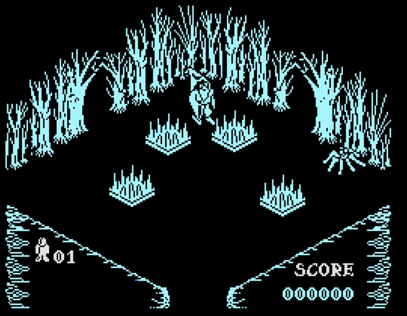 Screenshot of the game “Pentagram”, running on the C128 using the VDC chip.
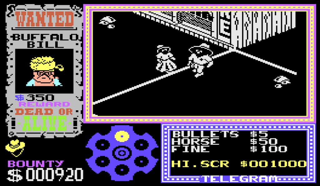 “Gunfright”, also running on the VDC
These games are good candidates as they use software sprites, in a bit-mapped mode.
Video RAM
The RAM used by the VDC is isolated from the main C128 memory map. It can only be accessed through two registers that are mapped to $D600 (address register) and $D601 (data register).
The following procedures must be used to read/write from the VDC RAM:
- put the required register # in the address register;
- wait for the ready bit in the address register to go high;
- store or load the value from the data register;
Here are the macros I’ve written for this:
.macro WriteVDC () {
	stx VDCADR
!:  bit VDCADR
	bpl !-
	sta VDCDAT
}

.macro ReadVDC() {
	stx VDCADR
!:  bit VDCADR
	bpl !-
	lda VDCDAT
}
Early C128 machines came with 16K of VDC RAM, expandable to 64K by added three additional 16K chips. Later models (C128, C128D-CR) had 64K RAM. The VDC is configured to use 16K or 64K modules, and we can check that configuration by reading bit 4 of register 28:
:SetBankConfiguration(15) // set bank 15
ldx #28
jsr READ_VDC
sta $fb
lda #010000
bit $fb
bne small
lda #$31
jsr $ffd2
rts
small:
lda #$30
jsr $ffd2
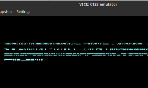
rts Running this program on VICE results in this, as it emulates a 64K model:
 An output of 1 means there is 64K available for the VDC chip.
Note
When your result is a
0it does not mean there’s only 16K in your machine, only that the VDC is configured to use 16K modules. So there still might be 64K available. I have not found a way to check this, apart from trying to write something outside the 16K. :)
Writing to the VDC RAM takes two steps:
- Set the update address where you want to write to;
- Pass data through the internal data register of the VDC (register 31);
This is the macro to set the update address:
.macro SetVDCUpdateAddress (address) {
	ldx #18
	lda #>address
	jsr WRITE_VDC
	inx

	.var a1 = <address
	.var a2 = >address
	.if( a1 != a2) {
		lda #<address // include if different from hi-byte.
	}
	jsr WRITE_VDC
}
Screen Data
The screen data area in the VDC is located at $0000-$07FF by default. It’s function is the same as screen memory in the VIC-II C128 main memory map ($0400 by default). As we have 80 characters in a row, it takes 2000 bytes, as opposed to the 1000 bytes on the 40 column display.
The current address in VDC RAM can be retrieved by reading registers 12 and 13. You can also change the address of the matrix data by writing a new value to these registers. This macro will read the current setting, and store it in $FB and $FC:
.macro GetVDCDisplayStart() {
	ldx #12
	jsr READ_VDC
	sta $fb
	inx
	jsr READ_VDC
	sta $fc
}
Writing to this area of RAM goes like this:
:SetVDCUpdateAddress($0000)
	ldy #0  // loop counter
	ldx #31  // internal data register of the VCD.
!:
	tya
	jsr WRITE_VDC
	iny
	bne !-
This puts 255 characters in screen memory. After each write, the update address in the VDC is incremented for us. Handy!
Attribute Data
Attribute data is located at $0800-$0FFF by default, and can be read or changed by modifying registers 20 and 21. Attribute data is comparable to VIC colour data, but it has more features. Characters can blink, be inverse (without these being part of the character definitions as with the VIC), underlined and more. Also, these attribute effects can be modified. for instance, the underline can be moved withing the character, enabling, for instance, a strike-through effect.
Each byte in the attribute data corresponds to a screen location, and it can be written to. Attributes are enabled by setting a bit in each byte:
7 - Character set
6 - Reverse video
5 - Underline
4 - Blink
3 - Red
2 - Green
1 - Blue
0 - Intensity
Attributes can be enabled or disabled (this is a global setting, allowing you to use the RAM for something else) by using bit 6 of register 25. So let’s play, by writing some bogus values to this area:
:SetVDCUpdateAddress($0800)
	ldy #0
	lda #%01110101
	ldx #31
!:
	jsr WRITE_VDC
	ror  // crazy stuff
	dey
	bne !-

	ldx #25  // write to this VDC register
	jsr READ_VDC
	ora #%01000000  // enable attributes
	jsr WRITE_VDC
	rts
This will be the result:
 Garbled attributes on a text of multiple ‘A’ characters.
Character Definitions
As on the VIC, the character definitions can be changed on the VDC. The definitions are located, by default, at $2000-$3FFF in VDC RAM and its config can be changed or read through register 28. As the VDC cannot access the character ROM at $D000, and because it has no character definition data by itself, the definitions are copied from ROM to VDC RAM when the C128 boots. As a VDC character is defined in a 8x16 grid, an 8 byte padding is added to each character data.
This is done by a KERNAL routine called DLCHR. We could utilise this routine, but it has some hard coded values, so here’s the macro I’ve made that steals this idea and makes it more flexible:
.macro CopyDefinitionsToVDC (address, address_end) {
	lda #<address
	ldy #>address
	sta $da  // pointer to start of data
	sty $db
	lda #>address_end
	sta $de  // high byte of data end

	ldx #$12   // write to $2000 in VDC ram
	lda #$20
	jsr WRITE_VDC
	inx
	lda #$00
	jsr WRITE_VDC

	ldy #0
loop:
	ldx #31  // VDC data register
!:
	lda ($da),y
	jsr WRITE_VDC
	iny
	cpy #8
	bcc !-

	lda #0  // add 8 bytes as padding
!:
	jsr WRITE_VDC
	dey
	bne !-

	clc
	lda $da
	adc #8
	sta $da
	bcc loop
	inc $db
	lda $db
	cmp $de  // done all?
	bne loop
}
To use this, you need to define the start and end of the definitions data. Here’s how to in Kick Assembler:
.pc = $2000 "character set"
charset:
.import binary "tetris_chars2.raw"
charset_end:
I’ve imported the char set created for my Tetris clone. Spot the counterfeit logo, after I’ve called this:
:CopyDefinitionsToVDC(charset, charset_end)
:Go80() 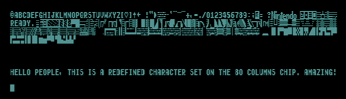 Making Tetris on the VDC should now be achievable
That was easy!!
Modify Font Display
The VDC can manipulate how characters are displayed. We can do fun stuff with it.
The spacing around a character can be changed, by using registers 22 (horizontal spacing) and 9 (vertical spacing). Here is some example code:
ldx #22
lda #%10110110
jsr WRITE_VDC

ldx #9
lda #11         // vertical spacing of char to 12.
jsr WRITE_VDC
This will result in:
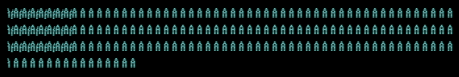 Adding spacing also makes a row longer, resulting in overlap
As you can see, more spacing is added vertically and horizontally. What is interesting to see is that all 80 columns are printed, but when a line wraps it is continued one pixel down, creating an overlap. The next line is started at the default position.
We can also control how MUCH of a character is displayed by modifying registers 22 and 23:
ldx #22
jsr READ_VDC
and #%11110000
ora #000100           // set horizontal display to 4
jsr WRITE_VDC

ldx #23
lda #3                // vertical display to 4
jsr WRITE_VDC
rts
Resulting in:
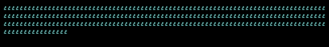 Only one quarter of each character is drawn
The spacing around the characters is not effected, but after setting the register values to 4, we only see a 4x4 grid of each character.
What do do with it? We can make fun fades, like:
	lda #7
	sta $fb
!:
	ldx #23    // affect vertical font display
	lda $fb
	jsr WRITE_VDC
	jsr DELAY
	dec $fb
	bpl !-
	rts
DELAY:
	ldx #50
	ldy #0
!:
	dey
	bne !-
	dex
	bne !-
	rts
Resulting in:
 Reducing how much vertically is drawn, we get a dissolve effect even though the character definitions are not changed
Conclusion
The VDC is a versatile chip and it’s sad to see that not much software was created to take advantage of it. The demo scene created some cool demos and games using the VDC, so all is not lost!
There is more to the VDC chip, and we’ll return to it later when needed. There’s scrolling, blitter functionality, bitmap mode and more.
There is no part 4 yet.