Introduction
You can find the other post in this series here: MEGA65 Evolution - Part 1
Welcome to the second part of this series which is all about memory. The MEGA65 does include a lot of RAM and can address more RAM than 8 bits can carry. How did we get here? How does it work?
Throughout the Commodore home-computer product lines there have been different approaches to using, managing and accessing computer memory. We got more memory, different kinds of memory, memory reserved for a specific purpose, and so on.
8 bit CPUs can address a maximum of 64KB (as seen in the previous post). How to manage this? Commodore has always been about the custom chip, and they were one of the first to introduce a dedicated MMU (Memory Management Unit) with the C128. But there have also been clever tricks to modify the memory map, from the CPU point-of-view.
Memory
The MEGA65 memory capabilities are what they are because of what happened before. So, before we begin, again, an overview of the memory evolution:
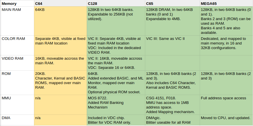 An overview of the implementation of memory in the Commodore computer family
C64
The C64 had 64KB of main memory. The ROMS were mapped inside this 64KB and therefore they were ‘taking up’ RAM. This is the reason there are so famously 38911 BASIC bytes free when you start the machine. Of course, RAM can be ‘reclaimed’ by switching ROMS off, using the bits of Address $1. Apart from this mechanism (a unique feature of the 6510 CPU) there was no memory management possible, apart from the VIC II video RAM pointer, which leads us to:
The main RAM was also used as Video RAM. The VIC II chip looks at a block of 16KB inside the main RAM and all video features (like sprites and screen memory) must reside inside this 16KB block. More on this in the video part of this series.
Colour Memory was provided by a separate 4KB block of memory that was always visible at $D800.
C128
Now things get tricky. The C128 introduced a lot of new stuff to make more memory possible and a few of these features carry on through the C65 and MEGA65, so it’s important.
Putting 128KB of RAM in a machine run by an 8 bit processor is asking for trouble :) We’ve seen that the address space of an 8 bit CPU is 64KB. Additional memory was added using separate physical banks. The C128 ships with two 64KB banks, and the C128 can look at one bank at any given time. This introduces the next issue: where to put essential data, registers and code that always needs to be available, no matter which bank is active? This was solved by declaring parts of the bottom and top memory pages to be active, no matter what. They called this ’common’ memory.
For more details on this mechanism, look at my post about managing memory on the C128, called Commodore 128 assembly - Part 2 As you see, things did not get simpler. And physical RAM bank switching is not exactly an elegant system. The C65 improved on this, but again, it was not making things simpler.
CBM added a Memory Management Unit (MMU) Co-processor specifically to manage these features. This concept was carried over to the C65, and improved.
Video memory management in 40 columns mode (VIC II) was the same as on the C64. What was different was the Video Display Chip (VDC) 80 columns memory management, and it’s relevant to the C65 evolution as well.
The VDC was provided with a dedicated memory bank. This was 16KB on the first C128 models and was later upgraded to 64KB. This memory was isolated and had to be addressed through VDC chip registers.
Colour, appearance and character set data for 80 columns mode all resided inside the VDC video memory. You can find the details on my page about VDC programming in the post called Commodore 128 assembly - Part 3. And we’ll get to the video evolution in a later post.
Memory content could be copied between the main RAM and the VDC RAM but it was slow as it all had to pass though a single VDC register. There was blitter (DMA type copying of memory) functionality added to the VDC chip, but it could only be used on the VDC video memory.
The C128 was a strange hybrid of all kinds but some of its memory features ended up in the C65 so it was essential in its evolution. How did these features evolve in the C65? Read on.
C65
The C65 came with 128KB DRAM. It was expandable to 4MB in total. The same principle as in the C128 was used: separate 64KB banks that could be “activated” by the use of the bank system.
A new concept to enhance flexibility was introduced: the memory mapper. With it, parts of the memory could be mapped to another parts of the memory map (in the same bank, or in another physical RAM bank) by the use of an offset. This potentially was more complicated, but it was optional and it gave more flexibility to the user. It deserves a dedicated blog post, really, as the feature is also present in the MEGA65.
Colour RAM is utilised in the same way as on the C128. There is 1KB for 40 column mode, and 2KB for 80 column mode. The location is fixed in memory.
The C65 also has a mode called ‘bit-plane mode’ which is something we will discuss in the VIDEO part of this series. In this mode colour information and storage is treated in a different way by the means of a programmable palette.
The C65 also introduced the DMAgic Coprocessor. It was able to access the complete 1MB system memory map of the C65 and to copy, mix, swap and fill memory blocks. It could be used directly from BASIC, a significant update to the implementation in the C128.
MEGA65
We’re getting into the big numbers now. The MEGA65 has a 28-bit address space, and it can access 256MB of memory. Remember: the CPU itself can only address 1MB of this memory only, and it is a 8-bit processor so it can only look at a single 64KB block at a given time: see Part 1 about the CPUs.
Depending on the mode the MEGA65 is in, this memory is viewed in different ways. This is a result of the evolution of everything that went before it. On top of that, the MEGA65 adds more memory management features, like the MAP command.
With the MAP command, we can map (heh) different areas of the complete MEGA65 memory map into the area the CPU is looking at. And, to make things more complicated, the BANK and Address $01 methods are also still available. Best practices are needed, evidently.
The MEGA65 has 16 banks of 64KB. The first two 64KB banks are arranged just as they were in the C65. The ROMS reside in this area as well, but the fun thing is: they are REALLY located in RAM. You can modify them once you clear the read-only flag!
The colour RAM (now 32 or 64KB) is located at a special location and must be accessed using DMA operations, or 32 bit addressing mode.
The Main memory of the MEGA65 can be classified as Chip RAM, a term that Amiga users might recognise, and here it is usable at 40MHz speed.
The MEGA65 yet again introduces more memory concepts: Attic RAM. This is a block of 8MB of RAM which is general purpose, but is slower in use (eg. not Chip RAM). To use it, or store data in it, you need to use the DMA functionality. It is not available on all models.
There are plans for memory expansion cards, insert-able in the port behind the trapdoor. This memory will be used in the same way as Attic RAM, but it will be called Cellar RAM. :)
And now we get to the important bit: The MEGA65 is not a static configuration as the older 8 bit machines. It will be more like the Amiga: different models, different configurations. Which means you need to be careful and very sure on the memory configuration of your programs. Trickier, yes, but lots of potential!
Concluding
That was a lot of information, and I hope you have a better understanding of the history of the memory options in the Commodore product line, and the end result: the MEGA65.
Thank you for reading!